Basics of ADSL and telephone
Telephone wires were originally designed to carry "Commercial Speech" between your home and the telephone exchange. This uses a band of frequencies from 300 to 3400 hertz. this system is called PSTN (public switched telephone network).
ADSL uses frequencies very much higher than this speech band to carry fast data traffic. ADSL systems use typically frequencies between 25 kHz and around 1.1 MHz.
Because PSTN and ADSL systems operate at different frequencies, they can be carried though the same wire pair at the same when the operating conditions are right. Voice calls operate between 300Hz and 3.4KHz, and include also DC power (0-72V DC at on-hook condition, typically 0-60 mA current and lower voltage at on-hook) and ring voltage (typically 40-80 V AC at 20-25 Hz frequency). The voice telephone system is matched to 600 ohm (or close to it) impedance at voice frequencies. ADSL technology operates between 26KHz and 1.1 MHz and is designed for around 100 ohms impedance. Because the two frequency spectrum do not overlap, it follows that both data and voice can be present at the same time on a single pair of copper wire. The different impedance have historical and technical reasons. The impedance of telephone wiring is typically around 100-120 ohms at the frequencies ADSL system uses. The cable impedance is somewhat higher at voice frequency range, considerably higher than 100 ohms, and where where historical 600 ohms impedance comes to picture (cable might not be exactly 600 ohms for voice, but that's what devices are designed for).
Why splitters / filters are needed
When ADSL and PSTN work at the same line at the same time, the electronics inside a normal telephone can be problem for high frequency ADSL signals: the ADSL signals can be attenuated (high capacitance on telephone input, possible resonances inside telephone, impedance mismatch) and ADSL signals can be heard as noise on some telephones (phone electronics demodulates high frequency signal outside it's operating range to voice frequency noise). In order to keep these systems apart and stop them interfering with each other it is necessary to separate the two components from the telephone line in your home.
This is where the Filter / Splitter comes in. The ADSL POTS Splitter / filter allows taking the full advantage of the 1.1MHz copper line frequency spectrum, by stopping the telephone and ADSL systems from interfering with each other.
An ADSL filter is normally a small plastic box with a short lead that plugs into your phone socket and two outputs, one for your ADSL Modem and another for a telephone. Some filters have only one telephone output in them. ADSL filter select the band of frequencies for each of the outputs, phone or ADSL, and send just the correct band to the appropriate socket. The phone output gets only telephone frequencies (from DC to 3.4 kHz) and the ADSL output gets the higher frequencies well (above 25 kHz).
For good system performance it is very important that all your other telephony equipment is separated from the ADSL signals by the use of a splitter / filter -- this equipment includes telephones, answering machines, "normal" computer modems, etc, etc.
Tips:
* All phones or other equipment must pass through a filter.
* Make sure that the ADSL signal is only passing through one Filter / Splitter.
* It can be the same Filter / Splitter for all of the phones.
How real life ADSL filters at home work
The signal to telephone output is generally just low-pass filtered so that voice frequencies (frequencies up to 3.4 kHz) get nicely though, but higher frequencies gets filtered. This filtering generally consist of LC low-pass filter designed to some suitable operating frequency between 4 and 20 kHz (between voice and ADSL bands). This kind of filter causes that the high frequencies of the ADSL signal will be severely attenuated (usually by at least 30dB with a good filter) so the signal reaching your telephone equipment does not contain such amount of high frequency signals that could cause noise. The telephone LC filter is also designed in such way that the filter impedance towards the line that carries ADSL signals is high at the high frequencies, meaning that those telephone equipment and cables related to them look like they are look to high frequency signals that they would be "disconnected from the main line.
The ADSL POTS splitter is simply a series of coupled inductors and parallel capacitors forming a low pass filter that attenuates the higher frequency ADSL data and permits only the voice frequencies to reach the telephone. The series inductor shows high impedance to high freqencies, so the ADSL signals on the line are not attenuated.
General design specifications for an ADLS filter should be something like this:
* Return loss at voice frequencies (against 600 ohms) would be should be good enough.
* Should not alter voice band frequency response too much
* Should not have too high series resistance (commercial filters seems to have between 50 and 100 ohms for whole loop resistance)
* Filter must pass the POTS tip-to-ring dc voltages (typically o-72V)
* Filter must pass ring voltages well (40V to 80V rms at any frequency from15.3Hz to 68Hz with a dc component in the range from 0V to 72V)
* Filter must
* All requirements must be met in the presence of POTS loop currents (usually around 0-40 mA, can be up to 120 mA in some cases)
The ADSL output from filter (if it has such thing) is generally unfiltered line signal (normal home ADSL devices are not to be bothered with line voltage and voice signals.
ADSL splitters at the central office
When the operator install ADSL system to the central office, they install ADSL splitter filters on the central office end of the telephone wire. The filters at the central office have basically the same functional needs as the home units, they need to be able to keep different signals separate, and separate those two signals to different outputs. Typical central office ADSL splitter filter is a device that ghas many filters built into one package. For each outgoing line there is one PSTN connection (goes to central office telephone central equipment) and one for ADSL connection (goes to DSLAM rack that terminates ADSL connections). Typical ADSL splitter in central office has series capacitors (blocks telephone line DC well, attenuates ring signal conciderably, but passes ADSL signals well) between line and ADSL output going to DSLAM.
Because ADSL splitter filter connects directly to the subscriber's loop media, it must also provide some surge protection from externally induced voltage which could damage any attached equipment or endanger humans interacting with the installed equipment. The ADSL splitters in the central office typically include overvoltage protection components to protect the ADSL DSLAM against overvoltages on the line. Some filtered ADSL outputs provide protection from the high frequency transient and impedance effect that occur during POTS operations (ringing transients, on-hook, off-hook transient and so on).
Here are some specifications related to ADSL splitters at central office:
* Ref. 1 : ETS 300 001 Attachment to Public Switched Telephone Network
* Ref. 3 : ITU-T K21 Resistibility of subscribers terminal to over-voltage and over-currents
Commercial ADSL filter example: ELEXI ADSL filter
The following photos, circuit diagram and text try to describe how ADSL filter sold by ELEXI (product number 440072 "ADSL puhelinsovitin USA/USA GP4C") works. This ADSL filter is picked as example because I happened to own one and the construction of this filter is quite simple (=easy to understand).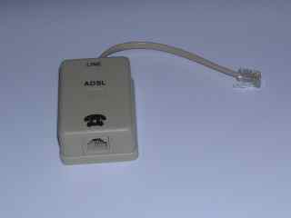


Figure 1: Circuit diagram of the filter circuit board electronics.
The phone line to central office (that carries ADLS and PSTN signals) goes to the left side of this filter and the phone goes to right side. This filter consists of an LC low pass filter made of the series connected coil (total impedance of 10.260 mH per wire) and the 22 nF capacitor across the wires. Those form the actual filter. There are resistors after this LC filter to make the filter properties have proper impedance matching for voice frequencies (should be around 600 ohms). This filter seemed to have one 1A fuse on the output to protect the circuit against some catastrophic damage (what this would protect against.
The total series resistance this kind of filter cause to one telephone wire was around 45 ohms, meaning that having this filter adds around 100 ohms to the telephone wire resistance. The series resistors and internal coil resistance reduces the impedance mismatches that just putting a capacitor across telephone, wires would cause. If we take a look at the circuit construction with only resistances and capacitance in it, it is pretty close to a simple model of 0.5 km of 0.5 mm telephone cable wire. The coil impedance at voice frequency would be at 20-200 ohms, causing some mismatch and attenuation at high telephone frequencies. The capacitor has impedance of around 250-2500 ohms at voice frequencies. Return loss at voice frequencies (against 600 ohms) would be acceptable with this kind of circuit.
The coils in this circuit are built to ferrite cores, boppin cores for highest inductance values and the 40 uH coils are wound to small ferrite toroids. My guest is that the coil part is constructed from three separate coils to make the filter to work well at high frequencies. The 10 mH coil has lots of turns, so at high frequencies it's performance might not be best (potential coil resonances etc.), but at those high frequencies those smaller value coils have already attenuated the signal enough. Getting three different coils in series gives best performance on all frequencies.
Source: Link
Labels:
ADSL
Subscribe to:
Post Comments (Atom)